Setting Up a Single-Channel System
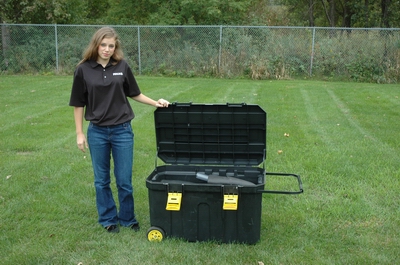
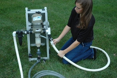
The 1-Channel System is packed in a large tool box (3′ x 2′ x 2′) that can be easily moved around the site with the attached wheels and extendable handle. The loaded box weighs approximately 100 pounds and contains everything needed to inject Newman Zone® into a 1″ or 2″ diameter well.
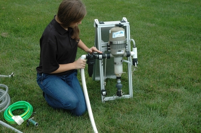
The Dosmatic™ proportional feed pump ismounted on an aluminum strut A-frame. The frame can either stand freely or hang from the side of a tote. The reverse side of the frame has a parts schematic, bill of materials, and contact information for the various parts suppliers.
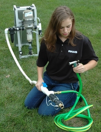
Attach the inlet hose assembly with the integral camlock fittings. Note that to the greatest extent possible, we have constructed our equipment with female/female hoses that attach to male fittings on the equipment.
Make certain that the inlet hose assembly is attached to the inlet side of the pump. An arrow indicating flow direction is molded into the pump motor housing. We have drawn a flow direction arrow on the top of the pump motor housing.
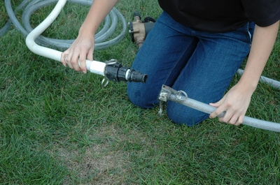
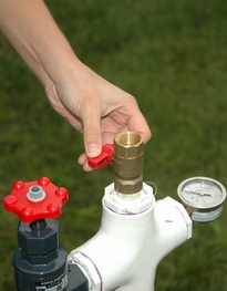
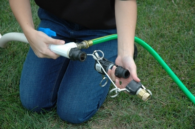 The end of the inlet hose assembly includes a stack of fittings that allows you to use either a 1″ female camlock, 3/4″ female camlock, or 3/4″ male garden hose on the end of your water supply line.
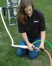 Attach your water supply line using the appropriate fitting. We have included a 15′ garden hose and nozzle immediately upstream from the shutoff valve. This provides service water to the site even when the injection pump is shut off.
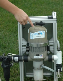
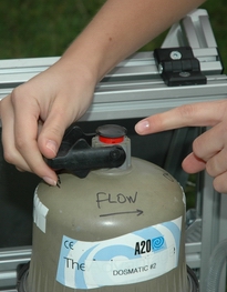
 Adjust the proportion of Newman Zone® to injection water. A Dosmatic™ A20-10% pump is shown. The A20-10% can be adjusted to a nominal feed ratio between 1% and 10%.
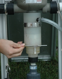
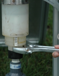
Remove the stainless steel, U-shaped anti-rotation pin from the outer cylinder and turn the inner cylinder with a smooth-jawed wrench. A 12″ adjustable wrench is the preferred tool (1-1/2″ capacity).
Adjust the inner cylinder until the desired proportion indicated by the scale on the inner cylinder lines up with the bottom edge of the outer cylinder.
The scale is located on a flat milled on the inner cylinder; it should line up with the holes for the anti-rotation pin when adjustment is complete. Then replace the anti-rotation pin.
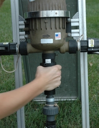
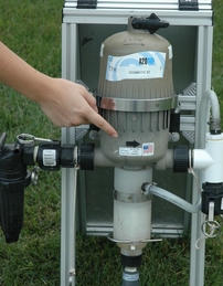
 The Dosmatic™ A30-5% pump can be adjusted to a nominal feed ration between 0.5% and 5%.
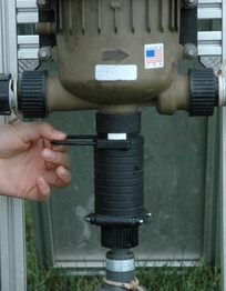
Remove the plastic anti-rotation pin from the outer cylinder and turn the outer cylinder by hand.
Adjust the outer cylinder until the desired proportion indicated by the scale on the inner cylinder lines up with the top edge of the outer cylinder.
The scale is located on a flat milled on the inner cylinder; it should line up with the housing for the anti-rotation pin when adjustment is complete. Then replace the anti-rotation pin.
 Place the screen end of the amendment hose in the source pail or tote of Newman Zone®. Attach the other end to the check valve at the bottom of the pump using the camlock fittings.
Because of the reciprocal motion of the piston in the pump motor, the fluid pressure in the three hoses, including the amendment hose, will sympathetically fluctuate. At high flow rates and inlet pressures, these fluctuations may be sufficient to “pump” the amendment hose out of the pail or tote. Restrain this motion with tape, cord, or bungees. Also be aware that this same motion can upset partially emptied pails.
 Attach the discharge hose to the pump outlet.
 Attach the 5′ vinyl hose to the discharge hose. Note that the downstream end of the discharge hose has a male/male 1″ x 3/4″ adapter. This adapter is necessary for the 1-Channel system and is removed when the 4-Channel expansion kit is used.
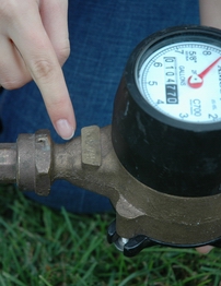
 Install the mechanical flow meter to the downstream end of the 5′ vinyl hose. Note the small arrow that indicates flow direction cast into the bronze housing.
The mechanical meter is used because it is reasonably accurate at very low flow rates, such as a fraction of a gallon per minute. It measures total flow volume and cannot be reset. Flow rates can be estimated by timing the sweep hand with a stopwatch.
The ones column in the odometer-like display does not move. Gallons and tenths of a gallon are indicated by the sweep hand.
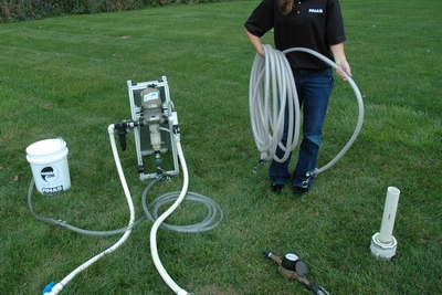 The injection system is connected to the wellhead by a 50′ vinyl hose.
 Install the reducing compression coupling on the well casing and tighten with two strap wrenches. The compression coupling that adapts our 1-1/2″ wellhead fitting to 2″ well casing is shown.
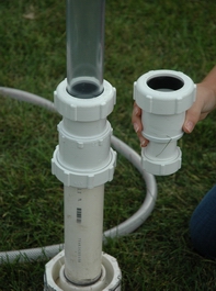
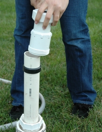
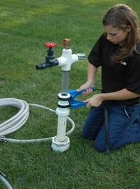 Install the wellhead fitting into the reducing compression coupling and tighten with two strap wrenches. The compression coupling that adapts our 1-1/2″ wellhead fitting to 1″ well casing is shown for comparison.
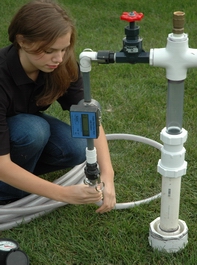
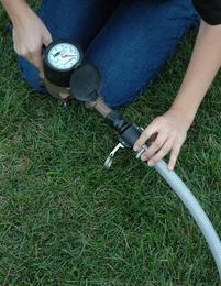
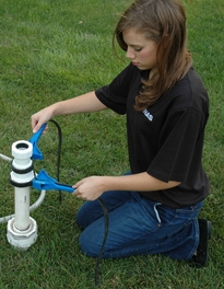
 Attach the digital flow meter to the wellhead fitting and the 50′ vinyl hose to the flow meter.
The digital flow meter provides both total flow and flow rate. However, at low flows, i.e., less than about 0.5 gmp, the paddle wheel stops turning and the meter ceases function. In such a circumstance, the mechanical flow meter will continue to provide an accurate measure of total flow and flow rates can be estimated by timing the movement of the sweep hand. Note that the mechanical flow meter can be installed near the well if desired.
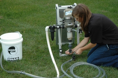
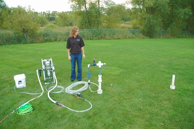
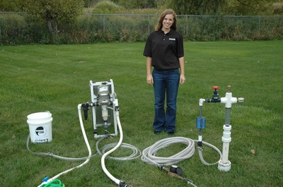 The completed installation of the 1-Channel System.
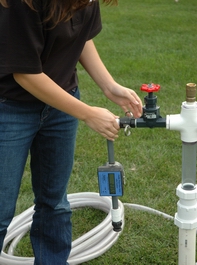
 Flow rate can be adjusted at the wellhead by using the throttling valve in conjunction with the pressure gauge (at the opposite end of the tee) and the digital flow meter.
The purge valve is used to vent air from the well casing after injection has begun.
 A Dosmatic™ pump makes loud clicking sounds as it operates. The sounds come from the check valves that sequentially open and close as they draw Newman Zone® and mix it with water.
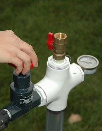
The proportional feed feature of later models of the Dosmatic™ pumps can be turned ON or OFF. Water will still flow through the pump when it is OFF, but no amendment is mixed with that water and the pump no longer makes any sound. Use the valve at the upstream end of the inlet hose assembly to shut off the flow of water.
Make sure that the lever at the top of the pump is in the ON position. The stem at the top of the pump motor housing shows a red band when the proportional feed is OFF.
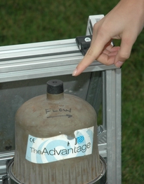
The proportional feed of older models is always ON. There is an unmovable knob at the top of such pumps.
 Do you wish to inject into more than one well at a time? Use our 4-Channel Expansion Kit and inject into as many as four wells simultaneously at rates as high as 5 to 7.5 gallons per minute.
For more information about our injection equipment, see the Tips for Injections page.